by Yu-kay
A Project I underwent, 2019
This page requires me to do some photo uploading. The report below is closer to 40 pages.
Jasmin Ivankovic
Start Date: 11/15/18
CprE 281
Final Project Journal
Lockpicking Game
For my final project, I plan to make a logic puzzle game in Verilog. I shall first explain the rules and how I will implement this game. The rest of this document will contain a detailed journal of how I made progress in the project. The sections will be divided as follows: Pseudo-Random Number Generator with register file, level changing machine, level logic machine, which includes Summing Levels, Bitwise XOR Level, Bitwise AND Level, Bitwise OR Level, Seven Segment Display with Enable, then Run Timer, Score Machine, and finally Composition. It will be further subdivided into date entries to mark my progress. At the very end, I go over the game’s overall performance in the final testing stage, and a brief conclusion.
Rules and Implementation
The game is somewhat simple in theory. It works as follows: you have three push-buttons that act as inputs, each holds an integer (one, two, and three respectively). These values can be used in a three key combination to unlock a locked safe. When you input a button, your input is verified on one of the four seven-segment displays, after your three inputs, the seven segments are again disabled by means of an enable line. To each level, you press the “randomize” push-button button. The game generates three random numbers that each range from one to three in a specific order and these are used as the correct passcode. In level one, after you enter your first three numbers, a kind of blind guess, then five green LEDs are used to display a binary number. They hold a hint to the correct combination which unlocks the safe, in later levels 6 red LEDs display a different hint. You may imagine this as being like lockpicking in Skyrim, turning the lockpick to break the lock; or, similarly, putting your ear to a safe while you slowly turn the dial. You only so many attempts/picks to get it right before the game resets and you restart on level one. Once you have completed each level, the other three seven-segments-displays will output the time (in minutes) it took you to crack the puzzle, this time determines how many points / how much money you get for the level. Your score is always viewable by means of flipping one switch. You can use paper and pencil to solve the puzzle, if the switch is off you can see how many attempts you have left. What will make each level more challenging is that the nature of the hint changes according to an algorithm. The game is as of now set to have five levels:
- level 1: random arithmetic sums
- level 2: total arithmetic sums
- level 3: bitwise XOR
- level 4: bitwise AND
- level 5: bitwise OR
11/16/18
By random sums I mean just the random numbers (correct code) is summed together and displayed on the aforementioned green LEDs. By total sums, I mean all the numbers (inputs and randomly generated numbers) are summed together and displayed on the same LEDS. For example, if you entered the combination 1 1 1 (in any order) and the machine generated the combination 2 2 2, The displayed number would be 9 (or 01001 in binary). Since your inputs are known information you can deduct 3 from 9 and be certain that the correct key sums up to 6. There are many combinations of three numbers (excluding 0) that sum to six, for example 1 2 3, or 3 2 1. That is how you solve any level, guessing the keys in the correct order.
The third level, XOR, is similar to the rest of the levels because each does a bit-wise operation on your initial guess with the generated key (in the correct order). The XOR operation takes two bits and compares them. For example, if you entered 3 for your first number and the random number generator generated 1 for its first number, the xor would be 2. How you solve this is by taking 2 and your input, 3, and doing the XOR operation again. Because XOR is its own inverse, you’d find that the first number was a 1 as the output on the red LEDs.
The fourth level, AND, doesn’t work exactly like XOR because AND is not its own inverse. The trick to this is that anything ANDed with 1 is itself. So, if you type 3s (11 in binary) for all three inputs, you will simply get the correct numbers in binary as the output on the same red LEDs.
Level five, OR, is the hardest because it takes work to guess the possible outcomes from the OR operation, but follows the same logic as previous levels.
11/24/18
By pressing randomize once at the start of the game you choose difficulty level 1, “common criminal”, which gives you 5 respawning lockpicks. By pressing it twice, you get difficulty 2, “seasoned hacker”, in which you get 10 non-respawning lockpicks. By pressing it a third time, you get difficulty 3, “lucky”, where you get 5 non-respawning lockpicks.
It should also be mentioned that this game has 2 cheat codes. One which increments the level, the other which gives you back all your picks. The codes will not be given in the rules and implementation section but can be found in the level changer machine logic included in this report.
11/26/18
A score machine was invented to make the game, well, a game (in a more proper sense). This was done by making what was originally just a timer work as a score keeper as well. There is a select line which outputs either the time or your score. The score was made by tracking the time it took you to complete a level. The code in the timer section will reveal how the game is scored is you’re interested. I will say that the max points available in a game are a “A00” (or 1000) because I’m using the same 3 seven segments I used for the timer. This score is very hard to get because you can only get a max of 200 points on each level by entering the correct key in under 20 s.
11/29/18
Furthermore, the difficulty represents a multiplier. Since there is more security, there is more money at stake. The equation for your total money is the following:
Money= points*10^difficulty. Where difficulty is an integer defined as either 1, 2, or 3. And points are your total points. This means the max amount of money is 1 million, if you’re on difficulty 3 (“lucky”).
There is one additional rule. If you are on your last pick/attempt, you can use the debug switch and get the passcode. Although there is no code stopping you from cheating, this can be done only once, meaning if your picks respawn, the rules say you cannot use debug again.
12/4/18
I made a design choice that slightly changed the game. The only difference is that you choose the difficulty by pressing 1, 2, or 3, or randomize which chooses one for you. If you choose the difficulty for yourself you must press randomize after, to start the game.
Pseudo-Random Number Generator
11/15/18
This part is challenging because Quartus Prime does not support the random number generation functions which, in my mind, almost ruined the whole project. I was thinking about scrapping it. The conditions of the random numbers would have worked perfectly with the $urandom_range(3,1) function, which basically generates a pseudo-random number ranging from 3 to 1. My first attempt at making a random number generator involved the SR-not-latch which can only have three possible outputs Q or ~Q, or Q and ~Q. This however fails to get a decently random number even if one the inputs is connected to a clock and the output is saved to a register file because the button press could limit it to two inputs 1 1 and 1 0. 0 1 would never be an input if the other input to the latch is logically synched to store values when the button is pressed. Thanks to our TA, Alex, I discovered that a random number can be generated with a shift register; the input is hooked up to the clock, and the clock input of the shift register is hooked up to a button. Then a decoder can be created to exclude the possibility of zero as an output.
Below the circuit and code that show you how the PRNG was created, and a simulation of it.
Fig. 1 Shift Register
Fig. 2 PRN Decoder
Fig. 3 Block Diagram of the PRNG with a range from 1 to 3
Fig. 4 Timing Diagram Simulation of the PRNG
11/16/18
The problem I found with this is that it takes four button presses to generate one number. Thus, it would take 12 button presses to generate 3 numbers, which is not a good enough design model. So, the new idea, again coming from Alex, was to use a counter and a decoder to generate three numbers. Below is the new and final design of my PRNG.
a.
b.
Fig. 5 a. and b. Counter circuit
Fig. 6 Counter Functional Diagram Simulation
Fig. 7 PRNG Decoder
This takes the counters value and assigns 3 two-bit numbers to it. It covers all the possible combinations and some repeats.
11/24/18
I noticed the odds of getting a sum of 6 is disproportionately high, so I made the numbers more random. The highlighted portion was changed.
11/16/18
I used two 1024 clock dividers to slow down the circuit. The input to the counter is a 50 Mhz clock. These were later removed to have all the clocks sync up in the final circuit.
11/21/18
I realized that a register file would be needed to load the random numbers into the game’s Verilog blocks.
Fig. 9 1-bit parallel load register
Fig. 10 6-bit parallel load register
The behavior of this register was surprising. It loaded the input only when clear and load were both high. Everything appears to be correct in the block diagram so I’m not sure why that is.
Fig. 11 The completed random number generator
Note that the register 6 not 4-bit. It was misnamed.
11/21/18
I found out that DFFs have negatively triggered reset lines, which now makes the registers behavior more clear. The upside to having the clear and load line connected to one toggle switch was noticed when testing level 1. When you set load and clear to 0, it shows only the inputted keys but not the random numbers in the sumr summation displayed on green LEDS 7-3. In level 2, it shows the inputted keys directly on red LEDS 10 – 5. These red LEDs were selected because they are directly under the 7-segment-displays which display the key inputs.
11/21/18
Level Changer
The level changing machine was made using two states and 3 sub-states. The commented code below explains the design.
I decided to first take in the random numbers from the random number generator as one 6-bit number and split them up when I send them into the level logic machine, which generates the hints for each level. Without the variable state to toggle the button presses, all three numbers (num1, num2, and num3) would be the same depending on your first key press. The state machine here only has two states, pressing buttons or checking if they’re right or wrong. This was not my first choice for the machine, it originally had 4 states. For some reason, this model froze each time on the third state, which made me come up with this design. Here are state diagrams for the original and final designs. Note that these figures are not exactly proper state diagrams. Propriety states that I would have to make each state’s output a uniform width and include every variable, including things that are useless for the general idea of the state machine, like seven segment display enable lines, and num1, num2, num3 from state 2, and all the other little discrepancies in the code. These were more so used to organize my thoughts, not to be exactly correct. If you are interested in seeing a more correct state diagram, look at my code and start crying because it’d be very difficult to draw (but maybe not to write out). Not to mention there are at least 2 state machines here that have interconnections but one (level logic) is has no output that goes to the other (level changer) besides the reset (“randomize”) button press condition (however, that was a little useless because the clock runs too fast for you to ever resister a button press during state 2).
Fig. 12 the old machine design
Note that there should be outputs from state 4 to levels 2, 3, and 4.
Fig. 13 This is the new state machine design
It has 2 states and 3 sub-states.
The first state is designed to take three button presses before going to state two. If at any point the randomization button is pressed, not only do the random numbers change, but the whole game resets and you start at level 0.
The above code is half the logic for curState==1. It checks if the input combo matches the random combo. If so, the level increases by one. If you win the game, it starts over.
Above is the reset of the code for the level changing machine. If the input combo is incorrect, miss is incremented by one. You are returned to typing numbers in at whatever level you are in so long as miss does not exceed 5. And again, if randomized is pressed, the game restarts.
11/23/18
Enables were added to make the seven segment displays only on when keys are entered and off after all 3 keys are inputted. If you forget what your inputs were, you can always turn the low toggle switch down and see the sum of your three key input. If you are on level 3 the XOR and load is low, you simply see your inputs in binary. In the later stages of the game, however, it is more important that you remember which order and which keys were entered, as it will not be displayed and could result in you losing the game.
11/23/18
Below is how the rest of the code was changed today.
The order of the code was changed to make the randomization button restart the game. For some reason while it was beneath all the key presses logic, it wasn’t restarting the game as was written in the code. Also refer to the first comment in the above picture, it toggles clear off. This was a problem which made the timer seem broken. It clear was getting toggled on and never reset to off while the timer ran.
The above code section is apart of the key input logic. What was added was noted by the fourth comment, a logic which turns on the seven-segment display after the key input. Also the second comment which clears the timer if it was stopped in the other state. This was only included in the first key entry logic, and would not be necessary in the other key entries.
In the other state, the seven segments are disabled.
11/24/18
A few new things were added. 3 difficulties and 2 cheat codes. The difficulties are common criminal, seasoned hacker, and lucky. In common criminal, you have 5 picks (or guesses) before its game over, and every time you beat a level they respawn. In seasoned hacker, you have 10 guesses and they don’t respawn. In lucky, you have only 5 guesses and they don’t respawn. Below is how they code was changed. Also, the bug mentioned in the progress entry on 11/23/18 was fixed. Randomize is now toggled properly.
11/26/18
Today I added code to this Level Changer to work with the score machine. Also, I fixed a couple bugs. The randomization button must be pressed after each completed level to make sure new random numbers are generated, and the timer starts after the first button press when the game starts or you complete a level. It used to start after the third button press. However, if that was left that way, the score would not increase if your first guess was correct because the timer has all zeros for the output.
The score is reset if randomize is pressed in the middle of the game, and when the game first starts or starts over.
The timer now starts at the first key entry.
12/4/18
The code which changes how you choose the difficulty is below.
11/21/18
Level Logic
The level logic machine was very simple to write. It outputs the hints of the levels.
11/23/18
The level logic machine was updated today.
As you can see from the above picture, it is much more elegant to use a case statement and one if statement to command the outputs for each level.
11/24/18
Further testing showed that level logic machine works better with if statements. I am still limited to only two working cases when using a case statement for some odd reason.
11/23/18
Seven Segment Display with Enable
The code is provided below.
- e is the enable line which turns the seven-segment off or on depending.
- It might have been more elegant to use a default statement for all other inputs, but this works too
The Run Timer, Clock Generator, and Score Machine
Below is the 1Hz clock generator code. It was made from a simple down counter which toggles a clock state at counter=0. The equation for the clock output division based on where the counter starts is
- Divider = 2 * counter_start + 2
If we set divider to 50 MHz, counter_start= 24999999 as is shown in the code.
“WinCounter” was the original name I gave to the run timer. Note that this name is not the best since it does display a time whether you won or lost a round. The commented code below explains the underlying logic for the timer.
Note: the counter is displayed on the seven segment displays only when enable is 0. This can be seen in fig. 13.
11/26/18
The Score Machine
Here is the code that generates a total score at the end of each level completion. It looks at how long it took the player to enter the correct score and increments veriables x2, x1, and x0 by a certain amount. After it is generated, you toggle the select line to either see your time or your score on the three seven segment displays.
Composition
11/21/18
Fig. 12 shows the original circuit when the game was almost complete but the timer seemed broken.
Fig. 12 The semi complete schematic
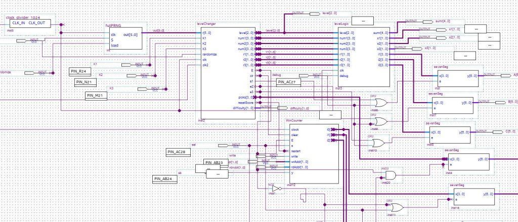
11/23/18
Fig. 13 The working final circuit
Note that “curState” has output pins. This was just used for debugging but not taken out.
Fig. 14 The clock dividers
Fig. 15 Picks Output
Picks was added to show you how many lockpicks (or guesses) you have left.
They slow the game down to a better rate. Also, notice that R is connected both to S of PRNG and randomize of the level changer code block. “Randomize” is also the name of what should be “Load”. This should’ve been corrected for clarity.
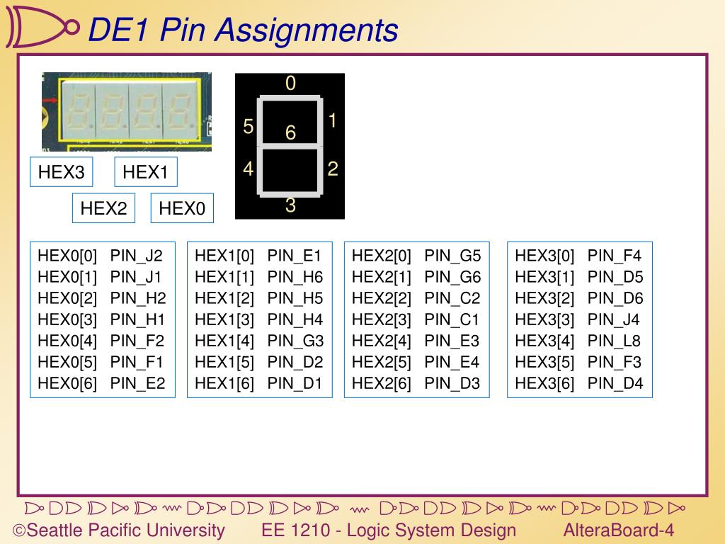
Fig. 15 Pin Assignments
This shows you the pin assignments for everything but the seven-segment displays.
11/29/18
I added two things to the composition. The first was a debug option which was just a conditional statement to display the random numbers on the seven segments if a switch was flipped on. For this to work, I also had to include OR gates to turn the enable on when ever this new select line was high. The actual code was very easy, just conditional operators for the outputs in level logic.
Fig. 16 Conditional Seven Segment Enable Lines
The other installment was to have the score be viewable at any point during the game. The same idea applied to this only to the win timer code.
The placement of this at first was above that previous end (at the top of the image), this caused a bug. The problems was that the else statement that runs when the timer is stopped caused conflicted with the condition to define the output when it was running. Easy fix. Also, the viewing of the score during the game conflicted with the left most seven-segment being active and displaying your picks number. So, although I needed or gates with the outputs, I also needed to hide picks if when you view the score, and, therefore, needed an and gate with the inverse of the select line and picks seven-segment enable line.
Fig. 17 More Conditional Seven-Segment Enable Lines
Performance Updates
11/23/18
Ultimately, the game works as desired. I solved several issues before it performed this well. A lot of the problems were making my Verilog code work correctly. Some problems, like the 2-state limitation for the game, were confusing but I worked with them. One performance issue was solved by slowing down the clock. This was more apparent when running at the PRNG by itself, the keys were more random with a slower clock. Now when playing the game, the pseudo-random numbers seem to be random each game. Towards the end of my troubleshooting, I fixed it so that the randomize button not only changes the random numbers but actually restarts the game. The only thing I can tell that is still lacking based on the performance is that pressing the randomize button after the game has started doesn’t reset pressed to zero. This means you are supposed to press randomize a second time, setting pressed to 1, which would allow you to start pressing keys. Although the code is written for this to happen, the second randomize button-press is apparently not necessary to start the game. It somehow overrides the code and sets pressed back to 1, because I noticed that the next keys can be entered immediately. This is a minor bug which I have not found a solution for. Otherwise, everything works as intended. Overall, the game’s performance is almost perfect.
11/24/18
I found and fixed the bug in my level change machine logic mentioned above in my previous entry. It was a case of not toggling the randomize button properly. I also added 3 difficulties, I call them “common criminal”, “seasoned hacker”, and “lucky”. I also hardcoded two cheat codes. The performance of the game is perfect now. I think it is complete.
11/26/18
I fixed a few newly discovered bugs and added a score keeper and system which created more bugs which were also discovered and fixed. The first came after having someone play the game and realizing that the random numbers were the same each level. The problem was immediately obvious, without pressing randomize, new numbers were not being generated. Then came the new score keeping machine which did not perform well until a toggle variable was added to tell it when to update the score and a reset input was added to tell it when to reset the score. However, the game now feels like a real game. It seems to be performing optimally. I think it is ready to demo.
11/29/18
More people have played the game and it is performing as desired. There were a few bugs that I fixed while additional features (those added in the composition section today) were developed.
Conclusion
Ultimately, I made a logic puzzle game in Verilog HDL and BDF formats that runs on Quartus Prime and is playable on Altera FPGA boards provided at ISU with the files provided in this report. This concludes my final project for EE 281, I had a good experience working on this project and learned a lot about programing in Verilog. It would not have been possible without the help of my section’s TA, Alex Campbell, who has said that I’ve become spiritually awakened in the process. It was worth the 60 hours I spent. I think if I hadn’t thought up my own project idea, I wouldn’t have put in this much effort. I believe this course should incentivize original ideas with bonus points (but that’s a whole different story because it might put a strain on the TAs when everyone starts submitting something different). Although it was original, Lockpicking should meet all the criteria requested in the project description. Furthermore, although it might’ve been the first, I hope it is not the last original/creative thing I do during my baccalaureate studies at ISU.
